Blog Archive

Saturday, November 30, 2024

Emerging Horizontal Drilling Patterns and Geometries: U-Lateral/Paperclip/Horseshoe Patterns, Multilaterals, Fishhooks, and Thermal Oil Play Multilateral Designs


     In recent years the impressive lengths of horizontal well lateral sections, approaching 30,000 ft in some cases, have been emphasized. However, there are other emerging horizontal and multilateral well designs that are being used to better access reserves and better optimize their production.

     It is not uncommon for directional drillers to have to steer around certain areas, often due to unleased acreage. I have worked on several wells that have turned the azimuth several degrees to avoid crossing areas where access is forbidden. I have also worked on many wells where the curve was drilled behind or to the side to maximize lateral footage.

     Multilateral wells have a single main wellbore and usually several shorter wellbores branching off. Other designs may include two main wellbores. These wells as well as multiple wells on a single pad require what is known as anti-collision analysis. This involves planning for each leg trajectory and not deviating too much from each trajectory.

     The U-shaped lateral has emerged as a preferred way to optimize acreage access and production. These are becoming more popular every year in applicable situations.

     Canada’s thermal oil plays require optimized reservoir access for different reasons. Some of these wells are stimulated with steam to produce the oil and these designs are how reservoir access is optimized.


The U-Lateral/U-Turn/Paperclip/Horseshoe Pattern

     The U-lateral is a preferred design for its simplicity and order. The goal is really to have two parallel well bores to take advantage of the optimum regional stresses. These laterals can be drilled with existing technology and as World Oil reports there are now about 70 of these wells drilled. They can allow an operator to better optimize their use of acreage. As noted, since the first U-lateral was drilled by Shell in 2019, there are now about 70, with 27 drilled in 2023 and more than that drilled so far in 2024.


Shell's 2019 U-Lateral. Source: Journal of Petroleum Technology


     The Delaware Basin is the most active area for U-laterals with 30 wells but as shown below they have been drilled in several U.S. basins. The Denver-Julesburg (JD) basin is second with 14 wells. Occidental and PDC lead in U-laterals with ten each. Chevron bought PDC and thus far has drilled five more U-laterals. Matador has noted cost savings on their U-lateral projects. The cost savings comes mainly from doubling the amount of horizontal that can be drilled with a single vertical section of the well.  Two-mile lateral is more economical than a one-mile lateral. Shell noted cost savings on their first U-lateral:

From an economic perspective, the horseshoe well saved 25% on rig time and about 20% on total cost compared with drilling two wells of the same lateral lengths. To a lesser degree, some savings was achieved on the completions side by requiring only one coiled-tubing run instead of two.”

     Hole sizes for U-laterals have varied between 6” and 8-3/4”. The turn has not been a problem with modern rotary steerable system (RSS) drilling motors as long as dogleg severity (DLS) stays as projected. Some wells can be drilled to total measured depth without tripping out. World Oil is the source of the following two graphics


Locations of U-Laterals. Source: World Oil


     In the case of Shell’s early U-lateral, the wellbores were left 1300 ft apart leaving room between them for another well. I wonder how often that is applicable and what the shortest distance achievable of the parallel wellbores of a single U-lateral is. It appears that a well in between the U would be required in most cases since that can really optimize spacing. I would think that a 10-12 degree turn per a hundred feet means that turning 180 degrees could take as much as 1800 feet with much of that section being at less-than-ideal orientation. Thus, I also wonder where frac stages may end on the U part of the lateral. I would think some of the U could host frac stages.

     A good thing about U-laterals as opposed to multilaterals is that U-laterals do not have junctions where the multilaterals connect to the main lateral. U-laterals utilize a single lateral which is less risky for several issues.

     Chinook Consulting’s Calin Dragoie wrote about some of the U-laterals in the Permian and Eagle Ford in Texas. The graphics below come from his post. The last two show how a U-shaped well provides ideal spacing if a lateral is drilled between the U. 


     As shown below, there is even a U-lateral drilled in Ohio, drilled by Ascent Energy in Harrison County, Ohio.


     Below is a graphic by Chinook Consulting where you can see some of the emerging U-lateral spacing and patterns being used in the Delaware and Midland portions of the Permian Basin and some of the companies drilling them.


Shell’s Fishhook Wells Offshore Brunei

     In the early 2000s Shell began drilling fishhook-shaped wells offshore Brunei in order to access reservoirs from below from an onshore or nearshore drilling site. These are not horizontal wells but deviated wells designed to reach reservoirs more economically. The shape is due to the fact that they drill ‘uphill’ to get to the reservoir from below due to the required geometries for turning the wellbore. This is an example of optimizing the situation to access reservoirs economically. As noted in the image below the Brunei reservoirs dip away from the shore.  


Multilateral Drilling

     Drilling multilaterals is generally complex and riskier than drilling regular horizontal wells. The well-funded oil majors have dominated multilateral drilling globally. Depending on the geological situation they may be the best way to access and produce the most hydrocarbons. One of the issues with multilaterals is simply that there are junctions between the main lateral and the smaller lateral that branch off from it. Each junction can be subject to problems, especially with drilling and casing. Some multilaterals are just wells with multiple main laterals of similar length. Others have one main lateral with others branching off.


     Multilateral well junctions are made using a process known as open-hole sidetracking. This makes a new branch. Wells drilled horizontally from another horizontal wellbore are called branches. If a new leg drills out of the horizontal plane to a different formation it is known as a splay. A guide to multilateral drilling from Drillingmanual.com gives six levels of junctions. They note:


The complexity of the multilateral drill depends on the integrity of the formation, the prevention of  water or gas coning, the requirements to isolate the main wellbore from the laterals, the requirement to reenter each lateral, and the requirements to isolate production from the laterals.”


     Junctions may be cased or uncased. Cased junctions are better for controlling production. Economics drives decisions to drill multilaterals. Sometimes there are geological reasons to drill them such as tapping into different reservoirs from complex fault blocks.


      A Level 1 junction has the main wellbore and the lateral left uncased at the junction, as shown below. This is the most common type of junction. The graphic below shows all six levels of junctions.


     In a Level 2 junction, the main wellbore is typically cased and cemented, while the lateral, or at least the junction, is left uncased. This is the second most common type of junction.


     The main wellbore in a Level 3 junction of multilateral drilling wells technology is cased and cemented, while the laterals are not cemented but cased only.


     A Level 4 junction has both the main wellbore and the laterals cased and cemented, as shown in Figure 2 above.


     A Level 5 junction builds upon the Level 4 system by providing pressure integrity at the junction. The pressure integrity is achieved in the completion by running tubing and isolation packers.


     A Level 6 junction attains full pressure integrity for maximum control. It is explained below and shown in Figure 2:


Level 6 junction is one in which full pressure integrity is achieved with the main casing string. There are two types of level 6 junctions: expandable metal junctions and splitter. They are used in new installations only because the expandable metal junction or splitter must be run as part of the casing string. The expandable metal junction requires under-reaming the hole where the junction will be placed to expand the junction before setting cement. The splitter junction requires drilling a much larger diameter hole from the surface down to run the splitter. For this reason, splitters are usually run at shallower depths.”


Canadian Thermal Oil Plays Multilateral Designs: Fishbone, Feather, and Stacked Multilaterals

     The graphics in this section come from Chinook Consulting Services. They have geosteered many of these Western Canadian Basin multilaterals wells and are the experts.

     In the late 2000s wells drilled in the Jean-Maie field in Northeastern British Columbia in the Western Canadian Sedimentary Basin, were commonly drilled as two or three-legged multilaterals as shown in the map and graphic below. Encana was a main player.


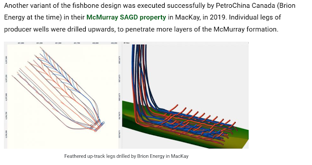
     Collector multilaterals drilled between existing pads of Bluesky wells in the Peace River oil sands were a precursor to the fishbone and feather multilateral patterns. The long and straight legs act as collectors and the many shorter lateral legs extend the drainage area. One well, drilled in 2016 has 47 legs and a total lateral length of 25,000 meters! Some fishbone and feather designs are shown below.


     Stacked laterals can also be of several types. They can be multilaterals drilled into the same formation with separate multilateral wells drilling into formations above and/or below. They can be a single multilateral well that accesses two or more vertically separated formations. The wine-rack geometry shown below is another type of stacked lateral where formations are alternated in adjacent legs. As also shown below, Devon drilled several stacked fishbone designs.


References:


Paperclip Wells: new well design in the Permian Basin. Calin Dragoie. February 10, 2024. (25) Paperclip Wells: new well design in the Permian Basin | LinkedIn

Why Shell Drilled a “Horseshoe” Well in the Permian Basin. Trent Jacobs. Journal of Petroleum Technology. February 10, 2020. Why Shell Drilled a “Horseshoe” Well in the Permian Basin

U-lateral drilling innovations: Making breakthroughs possible for directional projects. Gordon Feller. World Oil. October 2024. U-lateral drilling innovations: Making breakthroughs possible for directional projects 

Multilateral Wells Drilling Technology Full Guide. Drillingmanual.com. August 9, 2021. Multilateral Wells Drilling Technology Full Guide - Drilling Manual

Drilling Uphill. Paul Wood. GeoExPro. September 3, 2010. Drilling Uphill - GeoExpro

Multilateral, Feather, Fishbone: A look at Well Designs in a Mature Basin. Calin Dragoie. Chinook Consulting Services. October 26, 2020. Well design in a mature basin • Chinook Consulting


Friday, November 29, 2024

Decommissioning Offshore Oil & Gas Infrastructure: Costs, Recycling, Repurposing, Shared Infrastructure, and Onsite Waste Fluid Treatment


   Mature offshore oil & gas fields with declining production such as the North Sea are facing increasing decommissioning costs. It is estimated that over the next decade, about £20 billion will be spent on decommissioning.

OEUK’s Decommissioning Insight 2023 report offers a unique overview of the challenges and market opportunities in the sector which involve some of the biggest and most complex engineering projects ever faced in the North Sea.”

The report highlights that shutting down obsolete North Sea energy installations is a business opportunity worth more than £20 billion over the next decade, according to calculations by Offshore Energies UK (OEUK). The report also gives a detailed overview of requirements for decommissioning and recycling hundreds of oil and gas platforms in UK, Norwegian, Danish and Dutch waters.”


     According to the World Economic Forum:

The North Sea has more than 1,500 platforms and installations with an average age of 25 years.”

“Another 1,500 oil and gas platforms are more than 30 years old in the Gulf of Mexico.”

And in the Asia–Pacific region, more than 2,500 platforms will need to be decommissioned in the next decade.”

     While that is a lot to spend, the costs of decommissioning have been dropping and are predicted to drop a further 10% by 2028. However, that remains to be seen as costs have crept up over the past year. In the North Sea decommissioning of wells is set to account for 51% of expenditure of the next decade. By 2030, 180 of the 280 fields in the North Sea are expected to be no longer in production. 2100 wells are expected to be decommissioned in the next decade. Thus, for the region, decommissioning projects are going to be very common in the years ahead. It is important that different companies work together in decommissioning to save money, time, and emissions, and to find synergies. Several graphics from the North Sea report are shown below.


Structure and Materials Recycling: Mainly Above Sea, or ‘Topside’ Infrastructure


     The above sea, or ‘topside’ parts of platforms are typically dismantled and dragged onshore to be repurposed or recycled. The peak of onshoring these parts and materials is expected to occur in the North Sea UK in 2027, with 250,000 tons of material expected to come ashore. Parts like valves can be reused in other oil & gas fields. Concrete mattress removals for reuse elsewhere are becoming more common in decommissioning. In the North Sea, there are 40,000 concrete mattresses to be recovered by 2030, They can be reused in the construction and agricultural industries. As I recount later many platform substructures as well as sunken topsides could be used as reefs to enhance biodiversity and for use by divers. The graphic below shows three common methods of platform 'reefing.'


Repurposing: Keeping Platforms for Offshore Wind, Hydrogen, CCS, Floating LNG, etc.


     Many offshore platforms are repurposed for offshore wind infrastructure, floating LNG terminals, or infrastructure for hydrogen and CCS. A 2019 UKCS report explored possible scenarios of repurposing platforms for use in these ‘green energy hubs.’ Another potential innovation is electrifying the oilfields with nearby wind farms. Norway has led offshore electrification in recent years.

     Offshore oil & gas decommissioning is also informing offshore wind decommissioning. There are areas in the North Sea where offshore wind decommissioning will grow in the years ahead.


     As shown below, gas-to-wire electrification can be a very useful option to utilize stranded gas, decrease GHG emissions, and save costs.


Onsite Separation Technologies for Waste Fluids


     Decommissioning involves cleaning up a number of waste streams including oil sludge and oil-contaminated water. Typically, these contaminated fluids are shipped off to be treated elsewhere in a process known as “skipping and shipping.” However, treating these waste fluids onsite is now becoming an option. The deployment of separation technologies can save money and reduce emissions compared to other treatment options. One of these technologies utilizes centrifuging to separate particles by density. This has long been used in the oil & gas industry to remove solids from drilling mud. The unit shown below is a decanter centrifuge.


     A second separation device commonly used in decommissioning is a disc stack separator. Combined with a decanter centrifuge the two devices together can recover saleable oil from waste oil, remove solids, separate radioactive fluids, and separate water that can also be treated onsite in an effluent treatment plant. Wastewater with less than 30ppm of oil can be discharged into the sea and onsite treatment can get much of the water to that standard. Treating onsite saves quite a bit in transportation costs and subsequent carbon emissions. The article in World Oil mentions a decommissioning project where 8000 cubic meters of waste fluids and solids were treated onsite and 79% of the treated wastewater was below the 30-ppm limit. Onsite treatment can also operate during normal operations so that these systems can run more or less continuously, saving time during decommissioning. Treating onsite is also safer since it eliminates all transportation risks.


      The following section is excerpted from my 2022 book Natural Gas and Decarbonization:


Repurposing Offshore Oil and Gas Infrastructure: Rigs-to-Reefs


     Repurposing oil and gas infrastructure can take many forms. Offshore drilling and production platforms can be utilized for offshore wind or floating LNG functions or support. It has long been known that in certain places and at certain water depths and properties, the underwater parts of offshore platforms can support aquatic communities and even develop thriving reefs increasing ocean biomass. There are about 6000 offshore platforms globally and on average they provide about 2 to 3 acres of habitat {I am unsure of that number since other reports say that there are about 12,000 platforms globally}. That adds up to 15,000 acres {or 30,000}. A 2014 study published in the Proceedings of the National Academy of Sciences found that offshore platforms off the coast of California were “among the most productive marine fish habitats globally” and may be among the most productive ecosystems in the world. Thus, decommissioning of these platforms now can involve leaving much of the underwater components intact so that the artificial reefs keep providing ecosystem services. This can save companies millions in decommissioning costs. It is not applicable to all platforms and things to be considered include location, water depth, stability, structural characteristics, and age. Complete removal is still the main practice in the US but that is changing. In the past 30 years, about 500 platforms in the Gulf of Mexico have been retained as artificial reefs. This is an example of a circular economy. This has potential use for offshore wind and tidal platforms as well.[1] [2]  


References:


Oil's well that ends well: Recovering value, managing costs and reducing emissions during decommissioning. Rory MacKenzie. World Oil. October 2024. Decommissioning—Mackenzie (OSSO)

Decommissioning Insight 2023. The decommissioning outlook for the UK’s offshore energy industry. The UK Offshore Energies Association Limited (trading as Off shore Energies UK). Decommissioning-Insight-2023-OEUK-sac2nq.pdf

What to do with ageing oil and gas platforms – and why it matters. World Economic Forum. April 2, 2024. Ageing oil and gas platforms – here’s what to do with them | World Economic Forum

UKCS Energy Integration: Interim findings. Oil & Gas Authority. December 2019. ukcs_energy_integration-_interim_findings.pdf


[1] Oil platforms among most productive fish habitats. Jeremy T. Claisse, Daniel J. Pondella, Milton Love, Laurel A. Zahn, Chelsea M. Williams, Jonathan P. Williams, Ann S. Bull Proceedings of the National Academy of Sciences Oct 2014, 11 (43) 15462-1546. Oil platforms off California are among the most productive marine fish habitats globally | PNAS


[2] Hazelwood, Emily and Sparks, Amber. Rigs as reefs: An opportunity for creative, sustainable resource management. World Oil. August 2021. Vol 242 No. 8. Rigs as reefs: An opportunity for creative, sustainable resource management (worldoil.com)


Tuesday, November 26, 2024

EPA Proposes Stricter Standards for NOx Emissions at New Natural Gas Power Plants


     The EPA of Biden’s outgoing administration has proposed stricter nitrogen oxides (NOx) limits for new natural gas power plants. These standards were last updated in 2006. According to Utility Dive:

The proposal would ensure that new turbines built at power plants or industrial facilities — especially large ones that could operate for decades — would be among the most efficient and lowest-emitting turbines ever built,” the EPA said. “The proposal provides regulatory certainty for the power sector, while supporting the continued delivery of reliable and affordable electricity.”

The new rules would apply to most new, modified, and reconstructed fossil fuel-fired stationary combustion turbines. NOx compounds are a major contributor to smog and reducing emissions of them could help nearby communities reduce asthma and respiratory infections for vulnerable people, including children the elderly, and those with pre-existing illnesses. NOx compounds react with volatile organic compounds (VOCs) to form ozone and particulate matter.  The EPA announcement notes:

The proposed New Source Performance Standards (NSPS) are based on the application of combustion controls and selective catalytic reduction (SCR), a cost-reasonable and widely used add-on control technology that limits emissions of NOx. In addition, EPA is proposing to maintain the current limits for sulfur dioxide, which is well-controlled in this sector based on the long-term required use of low-sulfur natural gas and distillate fuels. The proposed stronger standards for NOx would apply to facilities that begin construction, reconstruction, or modification after the date of publication of the proposed standards in the Federal Register.”

To strengthen the NOx performance standards for new stationary combustion turbines, EPA is proposing:

To determine that combustion controls with the addition of post-combustion SCR is the best system of emission reduction (BSER) for most combustion turbines.

To lower the NOx standards of performance for affected sources based on the application of the BSER.

To establish more protective NOx standards for affected new sources that plan to fire or co-fire hydrogen, ensuring that these units have the same level of control for NOx emissions as sources firing natural gas or non-natural gas fuels.”

     The EPA is basing the requirements on turbine sizes and capacity factors (utilization rates). This is due to the higher relative costs of using SCR technology to mitigate smaller emissions sources and less utilized sources.

     The Sierra Club urged the incoming Trump administration to keep the proposed stricter standards but it is unclear whether likely incoming EPA chief Lee Zeldin will agree to that, especially as the focus of the incoming Trump EPA will likely be on deregulation or looser regulations rather than stricter regulations.


Selective Catalytic Reduction (SCR) Technology

     The chemical reactions involved in SCR technology are given below. SCR utilizes anhydrous ammonia, aqueous ammonia, or dissolved urea as reductants along with a porous catalyst such as titanium oxide, vanadium oxide, or zeolite materials. The choice of reducing agent is typically based on the turbine size. Smaller units typically utilize urea in solution while larger units are operated with aqueous ammonia. 


     According to an article about SCR technology in Power Magazine:

SCR selectively reduces NOx emissions by injecting ammonia (H3) into the exhaust gas upstream of a catalyst. The NOx reacts with NH3 and oxygen (O2) to form nitrogen (N2) and water (H2O), primarily according to the following equations:

4NH3 + 4NO + O2 ➝ 4N2 + 6H2O

2NH3 + NO + NO2 ➝ 2N2 + 3H2O

4NH3 + 2NO2 + O2 ➝ 3N2 + 6H2O

The catalyst’s active surface is usually a noble metal, base metal (titanium or vanadium) oxide, or a zeolite-based material. Metal-based catalysts are typically applied as a coating over a metal or ceramic substrate, according to NETL, while zeolite catalysts are typically a homogeneous material that forms both the active surface and the substrate.”

The performance of different catalysts is very dependent on temperatures. The presence of fly ash in coal plants complicates SCR configuration as the fine dust particulates can clog the small holes in the cells. The size of the openings or holes is known as the pitch. Thus, larger holes are used for coal-fired plants than for gas-fired plants which do not precipitate residual combustion materials or ash.

     Dan Johnson, VP at CORMETECH, an SCR system provider, makes the following comments in the Power Magazine article regarding SCR for gas units:

Gas units have set formulas that are commonly used. “Those formulas change, not with varying SO2 oxidation, but with varying temperature,” Johnson said. “As you go higher in temperature, you have to change the mixture of the catalytic metals that you’re using, because some of them will not perform well at higher temperatures. At CORMETECH, we pride ourselves on custom engineering our catalysts for every application, and it really is necessary to meet the performance requirements.”


     In the future, SCR technology may very well be combined with carbon capture technology and carbon monoxide abatement in a single unit as shown in the CORMETECH conceptualized graphic below.


References:


EPA proposes tightening NOx limits for new gas-fired power plants. Ethan Howland. Utility Dive. November 25, 2024. EPA proposes tightening NOx limits for new gas-fired power plants | Utility Dive

Selective catalytic reduction. Wikipedia. Selective catalytic reduction - Wikipedia

EPA Proposes Tighter Limits on Harmful NOx Emissions from New Stationary Combustion Turbines to Better Protect Nearby Communities. U.S. EPA. November 22, 2024. EPA Proposes Tighter Limits on Harmful NOx Emissions from New Stationary Combustion Turbines to Better Protect Nearby Communities | US EPA

Understanding Selective Catalytic Reduction Systems and SCR Design Considerations. Aaron Larson. Power Magazine. November 1, 2024. Understanding Selective Catalytic Reduction Systems and SCR Design Considerations

Could SCR Catalyst Technology Adoption Be a Roadmap for Power Plants Seeking Economical and Efficient CO2 Point-Source Solutions? Sonal Patel. Power Magazine. August 10, 2024. Could SCR Catalyst Technology Adoption Be a Roadmap for Power Plants Seeking Economical and Efficient CO2 Point-Source Solutions?

Monday, November 25, 2024

Solar Thermal Applications for Process Heat: Webinar Summary/Review and More


     Fossil fuels have long been the standard for producing heat for industry. They are cheap and available and produce heat suitable enough for medium and high-temperature applications. According to a 2021 paper in the Journal of Cleaner Production, the viability of solar thermal for process heat is dependent on several factors, both technological and economical:

The integration of solar thermal energy systems with the industrial processes mainly depends on the local solar radiation, availability of land, conventional fuel prices, quality of steam required, and flexibility of system integration with the existing process.”

     Solar thermal energy converts sunlight into heat while PV solar converts sunlight into electricity. Solar thermal requires solar collectors, which can be of several different types. Low-temperature collectors may be glazed, unglazed, Trombe walls, or solar roof ponds. Quotes are from Wikipedia.


“Glazed solar collectors are designed primarily for space heating. They recirculate building air through a solar air panel where the air is heated and then directed back into the building.”


“Unglazed solar collectors {aka. solar walls} are primarily used to pre-heat make-up ventilation air in commercial, industrial and institutional buildings with a high ventilation load.”


“A Trombe wall is a passive solar heating and ventilation system consisting of an air channel sandwiched between a window and a sun-facing thermal mass.”

“Solar roof ponds for solar heating and cooling were developed by Harold Hay in the 1960s. A basic system consists of a roof-mounted water bladder with a movable insulating cover.”

Solar air heat collectors in buildings are more popular in the U.S. and Canada than liquid heat collectors since the buildings have existing ventilation systems for heating and cooling.  

     Solar process heating systems are designed to provide large quantities of hot water or space heating for nonresidential buildings. Medium-temperature collectors can be used for water heating. Drying, cooking, steam distillation, and sterilization. High-temperature collectors may utilize parabolic mirrors and are used in concentrated solar thermal (CST) systems.

     Collectors for water heating include flat plate collectors, evacuated tube collectors, and some other types. One of the slides from the webinar (see below) lists these and their characteristics.

     Concentrated or concentrating solar thermal (CST) or CSP) can generate high temperatures for process heat. This technology is suitable for very high temps and can be used in mining, petroleum, minerals processing, chemical processing, petrochemical processing, and desalinization. 


  Some data from 2014 from NREL are shown below.


American Solar Energy Society Webinar Review

     This was a fascinating webinar presented by Bill Guiney of Artic Solar, for the Solar Thermal Division of the American Solar Energy Society. Guiney is a 42-year veteran of the industry.

     High-temperature solar thermal applications include power generation, air conditioning, and industrial process heat. Medium-temperature applications include hot water and air conditioning.

Low-temperature apps include things like pool & spa heating. Solar thermal can be utilized and optimized in a number of ways. Solar can be used to elevate groundwater temps for things like boilers, heaters, and heat pumps to reduce energy consumed.


     For facilities that use hot water the consumption in gallons/day is needed. Unfortunately, he says, there is no federal tax credit for solar thermal swimming pool heating. Hotels use natural gas, electricity, and propane, but could use rooftop solar for electricity and process heat. Schools can utilize solar thermal. Jails are another possibility. He notes that private jails seem to have no incentive to save energy. Flat plate collectors for hot water for these facilities. Greenhouses and district heating are also possibilities to integrate solar thermal.


     Guiney covers several project case studies showing the diversity of solar thermal process heat applications. Air & space heating, heat, dehydration, drying & cooling are the main processes. Air heating is needed for many projects. Dairies use lots of heat for both heating and cooling. They must get 110 degrees milk from cows lowered down to 37 degrees quickly which requires cooling. Sanitization and sterilization are also needed for dairy. These require heat. Solar thermal with its high temperature can purge their piping and heat exchangers resulting in more bacterial removal and higher quality milk. He mentions a project pumping honey and another pumping bitumen (tar). In both cases, the heating is to make it thin enough to flow. Steam for a distillery is another application. Solar thermal provides heat for boilers in a number of projects. Enhanced oil recovery projects require heat. Solar thermal can also assist in evaporation and distillation of oilfield water in water treatment projects. Meat processing and other food processing facilities use lots of process heat for sanitizing processes.


     He touches on solar cooling, noting that it is often misunderstood, but doesn’t really elaborate. He lists four kinds of solar cooling: 1) ammonia absorption, 2) lithium-bromide, 3) dehumidification, and 4) solar-assisted heat pump technologies. Waste heat from dehumidification can be regenerated back into the system.


     Solar thermal for assisting boilers must be low temperature, less than 100 degrees C because you can’t inject steam into a boiler, the water must be in liquid form. But it can be used to get the water most of the way there. Boilers can blend heated water and condensation return to optimize heat exchange. When evaluating projects, it is important to calculate all the requirements as well as the relative fuel costs and the relative GHG emissions.


     Guiney notes that a solar thermal system is simple, uncomplicated, and usually easily managed. He likes to add a 2nd circulation pump to his projects, to run the system with dual pumps so that if one goes down the system can still run at half pump rate. He also likes to size his systems low, at 70%, preventing the possibility of overheating. That seems unusual to me. It seems like there should be some other surefire way to prevent overheating, such as a digital management system with sensors and switches that can prevent overheating.

     He notes that there are several solar thermal performance simulators, including a free app from NREL called System Advisor Model (SAM). However, he also noted that he can basically do his own performance modeling.

     The last subject was subsidies, which are very good for solar thermal, especially the increase due to the IRA, which raised the federal tax credit from 26% to 30% with an additional 10% for a total of 40%. Tax credits are also saleable as are renewable energy credits (RECs). There are companies that buy tax credits. Non-profits can participate but have requirements. The USDA offers RECs, loan guarantees loans to 75%, and 50% USDA grants to agricultural and rural businesses, which often also include businesses in small towns and small cities in rural areas. It can mean as much as 90% subsidization! A project can see positive cash flow in the first year on those projects. While that may be amazing to the beneficiary, I have argued that is unfair to those who don’t qualify.

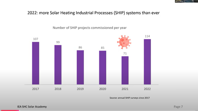
 Selected slides from the webinar are shown below.


A New ‘Thermal Trap’ Breakthrough Uses Solar Thermal to Create a Temperature Over 1000 deg Celsius


     Researchers at ETH Zurich have made a thermal trap to achieve temperatures for process heat above 1000 degrees C. This means that it can make high-temperature heavy industry process heat from low-carbon sources. This may eventually have implications for decarbonizing the heavy industry sector. It was a significant breakthrough, exceeding previous attempts by about 6 times.

“{CSP} plants typically operate at up to 600 degrees. At higher temperatures, heat loss by radiation increases and reduces the efficiency of the plants. A major advantage of the thermal trap developed by ETH Zurich researchers is that it minimizes radiative heat losses.”

The technology can also improve the efficiency of CSP plants.


References:


Solar Thermal Divisions Webinar: Solar Thermal Applications for Process Heat. American Solar energy Society. Webinar video. October 25, 2024. Solar Thermal Divisions Webinar: Solar Thermal Applications for Process Heat

Concentrating Solar-Thermal Technologies for Industrial Process Heat. Dr. Kamala C. Raghavan. Solar Energy Technologies Office. U.S. Dept. of Energy. Office of Energy Efficiency and Renewable Energy. May 2024. Concentrating Solar-Thermal Technologies for Industrial Process Heat

Solar thermal energy technologies and its applications for process heating and power generation – A review. Ravi Kumar K., Krishna Chaitanya N.V.V., and Sendhil Kumar Natarajan. Journal of Cleaner Production. Volume 282, 1 February 2021, 125296. Solar thermal energy technologies and its applications for process heating and power generation – A review - ScienceDirect

Harnessing the Sun: Innovative Thermal Trap Reaches Over 1000 °C Using Sunlight. Fabio Bergamin, ETH Zurich. SciTech Daily. May 28, 2024. Harnessing the Sun: Innovative Thermal Trap Reaches Over 1000 °C Using Sunlight

Solar for Industrial Process Heat Analysis. DOE. NREL. Solar for Industrial Process Heat Analysis | Energy Analysis | NREL

Solar thermal energy. Wikipedia. Solar thermal energy - Wikipedia

Solar thermal collectors. Wikipedia. Solar thermal collector - Wikipedia

       Lithospheric foundering, or delamination, refers to the loss and sinking (foundering) of a portion of the lowermost lithosphere from...

Index of Posts (Linked)