Monday, November 27, 2023

Next Gen Solar Technology: N-Type Cells, Perovskite Cells, Tandem-Junction Cells, Bifaciality, Floating Solar, Solar Canals, Inverter Design Optimization, Decoupled PV Thermal Systems, Agrovoltaics, and More


N-Type Cells: Negatively Doped and More Efficient Than the PERC Cells They Can Replace

     According to Chris Deline, a research engineer who leads the National Renewable Energy Laboratory’s photovoltaic field performance group, over the past five years the solar industry ‘entirely switched over’ from aluminum back surface field solar, or Al-BSF, cells to passivated emitter rear contact, or PERC, cells. Now the industry, he says, is poised to make another major switch to n-type cells from “p-type PERC to n-type tunnel oxide passivated contact, or TOPCon, cells. N-type cells have their wafers doped negatively using chemicals like phosphorus, while p-type cells are doped positively. Doping is the process of adding an impurity to the semiconductor to increase its ability to conduct electricity.” PERC cells still dominate but predictions are that the more efficient n-type cells will gain market share from 10% in 2022 to 60% within the next decade.


Perovskite-Based Tandem Junction Cells: More Efficient but There Are Chemical Stability Challenges

     Perovskite is a calcium titanium oxide mineral (CaTiO3) discovered by a German in 1839 in the Ural Mountains of Russia and was named after Russian mineralogist Lev von Perovski. Perovskite-based tandem cell technology is being produced and its use expanded. Tandem-junction cells have higher modular efficiency than single-junction cells. Utility Dive reported in July that “NREL announced a single-junction efficiency breakthrough on Oct. 25, reaching an efficiency of 27% with a gallium arsenide cell. In a release, the lab said researchers optimized the doping and structure of the top layer of the cell to minimize the negative impacts of defects.” Thus, improvements in solar efficiency are still occurring in single-junction cells as well.

     Tandem-junction cells or tandem solar cells are basically solar cells that are stacked. Perovskite cells are stacked above silicon cells, and each absorbs a specific range of wavelengths from the light spectrum. Single-junction silicon cells are subject to an efficiency limit known as the “Shockley-Queisser limit”. Scientists estimate that the theoretical efficiency limit for perovskite cells is 44% (double the average output of panels today) so if more improvements can be made this could eventually be a huge boon to the solar industry.


 Source: Hanwha Qcells


     First Solar and Hanwha Qcell are both investing in perovskite-based tandem-junction cells with Qcell announcing a $100 million investment in a perovskite-based tandem-junction cell production line. They plan to begin limited production by the end of the year and begin volume production in 2026. Hanwha Qcell describes the upsides and downsides of perovskite cells as follows:


     “Perovskite cells are created through a technique known as solution processing, an approach that not only makes perovskite manufacturing scalable but also holds the potential for remarkably low production costs. These thin-film panels aren't just efficient; they're also highly flexible, lightweight, and even semi-transparent, opening up innovative applications beyond conventional solar panels. With fewer materials needed for production and exceptional light absorption, they offer a cost-effective and compelling value proposition for companies in the solar industry.”


     “So, why doesn’t the industry just produce perovskite cells? The material, while highly efficient, faces issues related to stability and durability over time. They are more susceptible to environmental factors, like moisture and heat, which can degrade their performance and lifespan. This limited stability hinders their long-term reliability and commercial viability.”


     “Tandem cells, on the other hand, combine perovskite with traditional silicon cells in a way that leverages the strengths of both materials. By stacking different solar cells together, tandem cells broaden the captured spectrum of sunlight. Tandem cells typically consist of a perovskite layer on top, which absorbs short-wavelength light, including visible light and ultraviolet rays. At the same time, the silicon layer beneath it captures long-wavelength light, such as infrared rays. This dual-layer approach not only boosts efficiency and electricity generation — it also charges the future of the solar industry with new possibilities.”


Hanwha Qcells claims a maximum of 29.9% efficiency for their perovskite-based tandem-junction cells. The video below gives some great info about their future product.


Bifaciality: Higher Cost for Higher Efficiency. Perovskite Bifacial Panels Outperform Monofacial Panels for the First Time in the Lab

     Bifacial solar cells capture sunlight on both sides of the panel. Reflected and diffused sunlight is captured on the back-facing side. Bifacial cells are able to harness albedo radiation from the reflected sunlight. The challenge of bifaciality is that as back-side efficiency goes up there is some loss of front-side efficiency. Monofacial panels generally max out at 26% efficiency, which is great compared to the 17-18% max efficiency panels on my house. The NREL reported on research in July in the journal Joule that for perovskite single-junction bifacial cells the front face reached 23% and the back face reached up to 21% which could lead them to make 10-20% more power than monofacial cells. Perovskite cells and bifacial cells cost more so the efficiency and power output increases would have to overcome the cost to manufacture and deploy but that looks probable. According to the researchers: “simulations guided the design of the bifacial cell, and without that assistance the researchers would have had to experimentally produce cell after cell to determine the ideal thickness. They found the ideal thickness for a perovskite layer is around 850 nanometers. By comparison, a human hair is approximately 70,000 nanometers.” Thus, simulations, or modeling, guided the process of discovering the ideal thickness. In this case, one might say that modeling can lead to optimization. The graphic below is from the paper in Joule that describes the research on the promise of perovskite-based bifacial solar cells. The researchers note that a perovskite solar cell (PSC) “is uniquely suited to a bifacial structure, owing to its high absorption coefficients, long carrier lifetimes, benign and readily passivated surfaces, and proper band alignment with charge selective contacts.”


Source: Highly efficient bifacial single-junction perovskite solar cells. Qi Jiang, Zhaoning Song, Rosemary C. Bramante, Paul F. Ndione, Robert Tirawat, Joseph J. Berry, Yanfa Yan, and Kai Zhu. Joule. Volume 7, Issue 7, 19 July 2023, Pages 1543-1555. Highly efficient bifacial single-junction perovskite solar cells - ScienceDirect


      Now that perovskite-based bifacial cells have been proven to be competitive at lab scale, the next step is to scale up. Utility Dive’s Diane DiGangi sums it up: “Silicon cells remain slightly more efficient overall, with a record efficiency of 26.7% compared to monofacial perovskite cells’ record efficiency of 26%. Bifacial perovskite cells could allow the material to surge past silicon in terms of efficiency.” That should be considered amazing since perovskite cell designs only reached a meager 3% efficiency in 2006. In 2021 about 50% of solar cells on the market were bifacial. According to forecasts from 2020, this was not expected until 2024 as the graph below shows.


Source: Wikipedia


Inverter Design Optimization

     Inverters are a necessary part of a solar PV system that converts DC energy into AC energy. A 2012 study found that most service and maintenance calls for utility solar systems were about failing inverters. Some industry vets say this is because inverter development has outpaced inverter testing and standardization. There are different types of inverters and two types in particular have dominated: central inverters and string inverters and now a third type, hybrid inverters is growing in deployment. The central inverter model uses a single large inverter while a string inverter design uses many smaller inverters that work for a ‘string’ of panels. CapEx favors the central inverter design but OpEx favors the string inverter design. The installation cost of multiple string inverters is much higher than the cost of a single central inverter, but downtime costs are way higher with a central inverter. If a central inverter goes down, the whole plant goes down but if a string inverter goes down only a part of the plant goes down. With today’s supply chain issues downtime for maintenance can be more extensive. Hybrid inverter designs try to bridge the best of both central and string inverters and take advantage of modularity. Modularity can make maintenance easier and faster, which saves money and time. Solar company Sungrow makes inverters and touts its hybrid modular inverter design: “Sungrow designed its hybrid inverter with discrete functional modules to make troubleshooting and repairs faster and more cost-effective.” The company’s inverter design “also enabled the company to automate manufacturing for ramped up production, lower costs and a reduction of human errors in assembly. With today’s supply chain issues and increasing demand driven by the Inflation Reduction Act (IRA), the renewable energy industry needs strong suppliers.” Sungrow is a major supplier of PV solar inverters. Inverters are also used for battery energy storage systems. They shipped 47GW of inverters in 2021.


Floating Solar

     Floating solar has advantages and disadvantages. A major advantage is that it does not take up land space and it is cheaper to lease water space than land space for deployment. A disadvantage is that the solar panels are far from optimally tilted toward the sun. Floating solar is more common in Europe and Southeast Asia than in the U.S. There is an ongoing project to deploy floating solar in reservoirs controlled by the U.S. Army Corp of Engineers, the Bureau of Reclamation, and the Federal Energy Regulatory Commission (FERC). Regulatory and permitting issues are being worked out. One proposed project combines pumped hydro with floating solar in the upper reservoir, presumably to power or partially power the pumping of water back up to the upper reservoir. As the video below shows, researchers at Cornell are investigating what kinds of ecological effects floating solar could have on aquatic ecosystems.


Solar Canals to Reduce Evaporation in Drought-Prone Areas


     Another type of solar deployment over water is making solar canals in drought-prone areas where solar panels are placed above canals to both generate energy and slow the evaporation of water in arid areas. Unlike floating solar, these solar canal coverings can orient the panels to optimize orientation for sunlight. A first-of-kind project in Arizona involving the Gila River Indian Community and the Army Corp of Engineers aims to be the first solar-over-canal project in operation. Another similar project is in the planning stages in California. Solar canals even have other benefits. In India, solar canals have managed to help control weeds that were choking off canals. This can also lower herbicide costs and the effects of herbicides on the environment. Cooler microclimates below the panels have resulted in better solar panel performance over canals. A 2021 paper in Nature Sustainability notes the potential of solar canals in California. From the abstract:


Here we use regional hydrologic and techno-economic simulations of solar photovoltaic panels covering California’s 6,350 km canal network, which is the world’s largest conveyance system and covers a wide range of climates, insolation rates and water costs. We find that over-canal solar could reduce annual evaporation by an average of 39 ± 12 thousand m3 per km of canal. Furthermore, the financial benefits from shading the canals outweigh the added costs of the cable-support structures required to span the canals. The net present value of over-canal solar exceeds conventional overground solar by 20–50%, challenging the convention of leaving canals uncovered and calling into question our understanding of the most economic locations for solar power.”


Source: artist rendering. Interesting Engineering


Agrovoltaics: Dual Use Solar Generation with Crop Enhancement


     There are three basic types of agrovoltaics: 1) Solar arrays with space between for crops, 2) Stilted solar arrays above crops, and 3) Greenhouse solar arrays. Other activities such as grazing sheep to control grasses and weeds are called agrovoltiacs as well. According to Wikipedia: “Agrivoltaics, agrophotovoltaics, agrisolar, or dual-use solar is the simultaneous use of areas of land for both solar panels and agriculture. Because solar panels and crops must share the sunlight, the design of agrivoltaic facilities may require trading off such objectives as optimizing crop yield, crop quality, and energy production. In some cases crop yield increases due to the shade of the solar panels mitigating some of the stress on plants caused by high temperatures and UV damage.”


“The technique was originally conceived by Adolf Goetzberger and Armin Zastrow in 1981,[4] Agrivoltaics can refer to different methods of combining crops with solar panels, from conventional solar panels placed on top of crops, to greenhouses made of semi-transparent PV panels.”


It seems that finding synergies is the key to successful agrivoltaics. Modeling should be compared for different crops and regions. Moisture retention, cooling, and lowering UV exposure are some crop benefits of agrivoltaics as a result of shading. Tilt angles of the panels, panel height, and space between panels and panel banks can be optimized. One design is simply solar panels on greenhouses. Another design uses vertical bifacial cells as shown below (without crops).


Source: Wikipedia


     A 2022 paper in the Journal of Cleaner Production macro-modeled agrivoltaics in Japan, and found that certain areas were more suitable, particularly the rice paddy areas near to high energy consumption areas. Of course, like most solar PV modeling, the study also confirmed that concurrent battery storage and expanded electrical transmission would be required to avoid issues like curtailment and availability in low or no generation times.


Decoupled Photovoltaic Thermal Systems


     Decoupled photovoltaic thermal systems use a liquid to filter out excess heat and light. They draw away ultraviolet rays that would overheat the solar cells. It operates effectively as a cooling system. The liquid filter keeps solar cells cool while storing the heat away for later use. Water or nanoparticle solutions were common in the past as the liquid filters but are not very good at filtering harmful UV rays. Researchers at the Korea Maritime & Ocean University (KMOU) “found that fish oil excelled at filtering out excess light. While most water-based decoupled systems operate at 79.3% efficiency, the KMOU team’s fish oil-based system achieved 84.4% efficiency. For comparison, the team measured standalone solar cells as operating at 18% efficiency and standalone solar thermal systems at 70.9% efficiency.” The goal of decoupled PV thermal systems is to avoid accumulation of heat on the solar cells which lowers their operating efficiency. Waste-heat recovery via a small thermoelectric generator is the main model of these systems. The effect is similar to a combined-heat-and-power system.

     An October 2022 paper in Renewable and Sustainable Energy Reviews describes the state of the new technology of decoupled PV thermal systems as follows: “Thermal decoupling of the photovoltaic (PV) and photothermal (PT) modules has been successfully implemented by employing the spectral separation technique, which is conducive to the thermal damage prevention of the PV cells caused by the absorption of unavailable photons. Moreover, the thermally decoupled spectral splitter-assembled PV/T (SPV/T) system has also achieved high-grade output heat while utilizing the full spectrum of solar energy. It has been widely reported that recovering the output thermal energy from the SPV/T system is an effective approach to improving the overall solar energy utilization efficiency. However, due to the limitations of optical performances of spectral splitter and heat transfer coefficients of the heat sink, the up-to-date solar energy utilization efficiency is still lower than the theoretical expectation.” Research is ongoing for thermal energy recovery in these systems.

     Research in 2022 revealed that by taking advantage of radiative cooling solar panels could be modified to capture some energy at night. The new design uses a thermal electric generator and a heat sink to capture energy from the temperature difference of the solar panels and the ambient air, as shown below.  


Source: Nighttime electric power generation at a density of 50 mW/m2 via radiative cooling of a photovoltaic cell. Sid Assawaworrarit, Zunaid Omair, and Shanhui Fan. Applied Physics Letters.  Volume 120, Issue 14. April 4, 2022. Nighttime electric power generation at a density of 50 mW/m2 via radiative cooling of a photovoltaic cell | Applied Physics Letters | AIP Publishing


Other Solar Innovations


     Other solar innovations include bigger panels up to 650W in output, panels with better bifacial solar capture, “different ingot and wafer types, wafering techniques and cell structures, or module architectures, along with cheaper, simpler and more resilient racking systems.” Solar materials recycling is also advancing, with particular focus on recycling the tellurium and cadmium from CdTe panels. Tellurium availability is dependent on China. Improvements in tellurium recovery are being implemented.


References:

More powerful, resilient and versatile: The next generation of solar tech is emerging. Diana DiGangi. Utility Dive. November 16, 2023. More powerful, resilient and versatile: The next generation of solar tech is emerging | Utility Dive

How inverter design contributes to long-term profitability of solar and storage. Utility Dive. Feb. 6, 2023. How inverter design contributes to long-term profitability of solar and storage | Utility Dive

‘Bifacial’ perovskite solar cells could produce more energy at lower costs, NREL finds. Diane DiGangi. Utility Dive. July 20, 2023. ‘Bifacial’ perovskite solar cells could produce more energy at lower costs, NREL finds | Utility Dive

Hybrid Tandem Solar Cells. National Renewable Energy Laboratory. Hybrid Tandem Solar Cells | Photovoltaic Research | NREL

Arizona's solar-over-canal project will tackle its major drought issue. Can Emir. Interesting Engineering. November 24, 2023. Arizona's solar-over-canal project will tackle its major drought issue (msn.com)

First solar canal project is a win for water, energy, air and climate in California. Roger Bales. The Conversation. February 22, 2022. First solar canal project is a win for water, energy, air and climate in California (theconversation.com)

These cutting-edge solar panels can even generate electricity at night — here’s how they work. Ben Stern. The Cool Down. November 21, 2023. These cutting-edge solar panels can even generate electricity at night — here’s how they work (msn.com)

News Release: Bifacial Perovskite Solar Cells Point to Higher Efficiency. National Renewable Energy Laboratory (NREL). July 17, 2023. News Release: Bifacial Perovskite Solar Cells Point to Higher Efficiency | News | NREL

Highly efficient bifacial single-junction perovskite solar cells. Qi Jiang, Zhaoning Song, Rosemary C. Bramante, Paul F. Ndione, Robert Tirawat, Joseph J. Berry, Yanfa Yan, and Kai Zhu. Joule. Volume 7, Issue 7, 19 July 2023, Pages 1543-1555. Highly efficient bifacial single-junction perovskite solar cells - ScienceDirect

Perovskite Tandem Cells: Shedding Light on the Future of Solar Energy. Hanwha Qcells. How Perovskite-Based Tandem Cells Can Scale Up Solar Energy (hanwha.com)

Tandem Solar Cells. University of Edinburgh. The Solar Spark. Tandem Solar Cells | The Solar Spark (ed.ac.uk)

Q CELLS Massively Investing in Perovskite-silicon-based Tandem Cells. Business Korea. May 17, 2023. Q CELLS Massively Investing in Perovskite-silicon-based Tandem Cells - Businesskorea

Energy and water co-benefits from covering canals with solar panels. Brandi McKuin, Andrew Zumkehr, Jenny Ta, Roger Bales, Joshua H. Viers, Tapan Pathak & J. Elliott Campbell. Nature Sustainability volume 4, pages609–617 (2021). Energy and water co-benefits from covering canals with solar panels | Nature Sustainability

Nighttime electric power generation at a density of 50 mW/m2 via radiative cooling of a photovoltaic cell. Sid Assawaworrarit, Zunaid Omair, and Shanhui Fan. Applied Physics Letters.  Volume 120, Issue 14. April 4, 2022. Nighttime electric power generation at a density of 50 mW/m2 via radiative cooling of a photovoltaic cell | Applied Physics Letters | AIP Publishing

Agrivoltaics. Wikipedia. Agrivoltaics - Wikipedia

Modeling of large-scale integration of agrivoltaic systems: Impact on the Japanese power grid. Ruth Anne Gonocruz, Shuichi Uchiyama, and Yoshikuni Yoshida. Journal of Cleaner Production. Volume 363, 20 August 2022, 132545. Modeling of large-scale integration of agrivoltaic systems: Impact on the Japanese power grid - ScienceDirect

Researchers discover unexpected material can boost solar panel efficiency: ‘Effectively absorbs ultraviolet … and near-infrared wavelengths’. Jane Donohue. The Cool Down. November 25, 2023. Researchers discover unexpected material can boost solar panel efficiency: ‘Effectively absorbs ultraviolet … and near-infrared wavelengths’ (msn.com)

Recent progress in thermal energy recovery from the decoupled photovoltaic/thermal system equipped with spectral splitters. Wenpeng Hong, Boyu Li, Haoran Li, Xiaojuan Niu, Yan Li, and Jingrui Lan. Renewable and Sustainable Energy Reviews. Volume 167, October 2022, 112824. Recent progress in thermal energy recovery from the decoupled photovoltaic/thermal system equipped with spectral splitters - ScienceDirect

Bifacial solar cells. Wikipedia. Bifacial solar cells - Wikipedia

Saturday, November 25, 2023

Soil Pollution Assessment and Remediation: State of the Science, Trends, and New Techniques


    The UN’s FAO and UNEP write in their 2021 Global Assessment of Soil Pollution that: “Soil pollution is one of the main threats affecting soil health worldwide. However, soil pollution is {more} unique than other threats such as erosion or salinization: it is difficult to perceive with the naked eye, and its effects are only visible when the level of pollution causes acute effects on the environment and human health. Soil has the ability to filter, buffer, retain and degrade contaminants, in which components such as soil organic carbon, organisms, pH or type of clays and other mineral complexes play a key role.” That UNEP/FAO global assessment is my main source for this post which I summarize and paraphrase quite a bit here. It is also the source of all the graphics. The first graphic shows a macro model for the fate and transport of contaminants. 


     Soil pollution can be compounded over time in the same area which can result in ‘cocktails’ composed of multiple contaminants. Soil pollution can affect humans, flora, fauna, and ecosystems. There are both natural and anthropogenic sources of soil pollution. Soil pollution is often diffuse pollution rather than point-source pollution, makes it more difficult and more expensive to remediate. The graphic below shows a chemical classification of common soil contaminants. Not listed are emerging contaminants such as PFAS and microplastics. Microplastics are classified as incidental nanomaterials. Other nanomaterials are naturally occurring (such as volcanic ash) or manufactured (such as paints & pigments).


     Inorganic heavy metal trace element pollution in soil can be significant and can affect human, animal, plant, and ecosystem health. These pollutants are often persistent as they do not break down easily into non-harmful components. Their reactions in living cells are what cause harm. Radionuclides, either naturally occurring or from anthropogenic activity such as uranium mining, cause harm directly due to the radiation. Organic, or carbon-based contaminants, are mostly anthropogenic synthetic chemicals. These include pesticides, industrial chemicals, household chemicals, and refined hydrocarbons. Some are naturally occurring such as those deposited by wildfire smoke residue and volcanic eruptions. Naturally occurring human-extracted hydrocarbons like oil and natural gas liquids are included as well. Many of these substances, whether synthetic or natural, are or produce volatile organic compounds (VOCs) and polycyclic aromatic hydrocarbons (PAHs). Organic contaminants tend to be persistent in the environment and are toxic at varying levels. The most persistent ones are known simply as persistent organic pollutants (POPs).

     The FAO/UNEP report lists the variables of soil pollution as follows:

The extent and duration of soil pollution and the risk of harm of a specific contaminant or contaminant class depends on several determinants:

- the chemical nature of the contaminant; that is, inorganic compounds versus organic compounds;

- the inherent physico-chemical properties, for example, chemical structure, volatility2, water solubility, lipophilicity3, lipophobicity;

- the inherent toxicity of the compounds in their various forms;

- parameters describing the interaction and transformation of the compound with environmental media and biological organisms such as solution partition coefficients, decay rate of radionuclides, metabolization (degradation) rates;

- the source of origin and pathway to the environment, for example, geogenic versus anthropogenic, direct release or disposal in soil versus atmospheric deposition;

- place and time of emission of contaminants;

- emission quantities;

- soil concentration and analytical detection values;

- bioavailability and/or toxicity of contaminants, as well as species (e.g. chromiumIII vs chromiumVI) or transformation products (e.g., DDT vs DDE), depending on environmental conditions (e.g. soil pH, moisture, weathering conditions);

- land use of and sensitivity to receptors in affected areas; for example, agricultural and forestry activities, recreational, residential or industrial areas.


Effects of Soil Properties on Contaminants

     Soil properties affect the fate and transport of contaminants. Contaminants can accumulate, transform, or degrade as they move through the soil matrix. Soil can buffer and filter contaminants to a certain extent, which can trap and dilute them adequately before they reach groundwater. Both chemical and biological processes occur of many different kinds. Soil texture, structure, pH, organic matter, mineralogy, moisture, temperature, and biodiversity all affect the fate and transport of contaminants. Plants and animals can also affect contaminant fate and transport by taking up contaminants or subjecting them to biological processes.


Sources of Soil Contamination

     Soil pollution types are often a result of land use. Pesticides are often a major contaminant in agricultural areas. Asbestos contamination may occur in soils near old buildings. Sewage systems carry biological contaminants and household chemicals in abundance. The use of treated or non-treated municipal wastewater in many places can be a major source of contamination. Polyethylene plastic films used for mulching can contaminate agricultural areas with microplastics. Urban pesticides are a contaminant source in urban areas. Combustion particulate products that land and accumulate nearby are contaminants in those areas. They often contain concentrated amounts of heavy metals. Highly concentrated forms of combustion products like massive piles of coal ash from coal-fired plants can highly contaminate nearby soil, surface water, and groundwater. Raw sewage is a major contaminant in some places. Erosion and runoff can spread contamination but also dilutes it. Municipal solid waste from landfills is mixed with soil and layers of barriers to decompose into biogas which is now often collected and utilized but there are also toxic liquids that leach from landfills. Landfill leachate can be highly toxic and monitoring wells around landfills look for it and attempt to quantify it and model its transport. That leachate is also often collected for further sequestering. Health-care waste has its own dangers and protocols. Electronic waste is a newer form of waste that has issues as well. Some toxins leach out. Recycling is done but is not economically viable in most circumstances. Industrial waste streams can be quite large and can affect soil. Waste from oil and gas, mining, and manufacturing is quite common and widespread. Leaking wells can add hydrocarbons and saltwater to soil. Mine tailing piles can mix concentrated heavy metals and radionuclides into the soil. Industrial effluents can leach into the soil. As the graphic below shows, pollutants are also subject to global processes which can transport them and even accumulate them quite far from their source areas. Soil dust can be carried by the wind all over the globe.


Soil Pollution Remediation

     Since water tables often reach into soil and since groundwater moves contaminants it can increase contaminant dispersal within soil. Therefore, groundwater and soil remediation often overlap. The goal of remediation is to eliminate or thoroughly isolate the source of the contamination. This is in contrast to contaminant management and adaptation, which seek to remove contamination by cutting off exposure pathways or by removing the receptor. As the graphic below shows, the costs of remediation per volume of contaminant released rise the longer a release is left un-remediated as the contaminant spreads and saturates the local soil.


Once contamination is discovered and assessed there is a workflow to achieve the goals of management and remediation. This may include stopping further contaminants from being released, covering the area with an impermeable layer to prevent further contaminant migration through the soil with rainwater and vapors from getting too heavy in the air, danger warnings, signage, fencing, and restriction of food and water production in the polluted zone. UNEP/FAO note that most frameworks on soil remediation have the following guidelines: Define the remediation objectives. Design the remediation strategy. Implement the remediation strategy. Finalize including monitoring and long-term aftercare. Defining the objectives is the goal of site assessment and site investigation. These may be done with techniques such as soil vapor probes and groundwater monitoring wells. Who is liable and responsible for the contamination and who pays needs to be determined at this stage. Remediation strategy design is dependent on many factors determined through assessment. All regulatory considerations and available technologies should be evaluated. Procurement, on-site health and safety, waste disposal, and monitoring need to be considered in the design. Close monitoring and management during the implementation phase of remediation is required. Finalization depends on the goals of remediation, whether they were to eliminate contamination and return of the site for normal use or they were to isolate the contamination. Isolated contamination will require more and longer monitoring. The graphic below shows the stages of remediation of a contaminated site. 


Soil Remediation Technologies

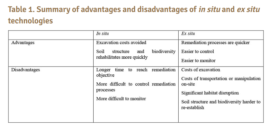
    Soil remediation technologies are classified in two ways. One is that they will be either biological treatment methods or physical/chemical treatment methods. Remediation technologies may also be in situ or ex situ methods. The soil remains in the ground for in situ methods but is excavated and stored elsewhere for ex situ methods. A recent example of ex situ remediation is the February 2023 Ohio train derailment and chemical spill where contaminated soil was excavated and transported to special hazardous waste landfills. Where applicable, biological-based in situ methods can be the cheapest and most effective soil remediation technologies. However, in situ treatment can take longer to remediate and bioremediation is only applicable to certain contaminants. The table below compares in situ and ex situ advantages and disadvantages.


In Situ Biological Treatment


     There are many methods of biological-based or nature-based remediation in situ remediation. Microorganisms, soil macroorganisms (such as earthworms), or plants may be utilized. Nature-based techniques can successfully remediate soils contaminated with petroleum hydrocarbons, chlorinated solvents, polycyclic aromatic hydrocarbons, pesticides, and trace elements. Bioremediation typically refers to a nature-based in situ method that utilizes microorganisms to break down and degrade organic pollutants. Aerobic or anaerobic bacteria may be used depending on the pollutants and circumstances. Aerobic bacteria are used to bioremediate non-chlorinated or slightly chlorinated hydrocarbons while anaerobic bacteria are used for more heavily chlorinated hydrocarbons. Bioremediation may include biostimulation, where the soils microorganisms are stimulated to better degrade the pollutants, or bioaugmentation, or enhanced bioremediation, where other microbes are introduced to degrade the pollutants. Soil properties can be enhanced by nutrients, pH adjustments, and temperature control to make bioremediation more effective. Bioventing and biosparging work by adding air to the soil to enhance aerobic decomposition reactions. Bioventing is air injection into the vadose zone above the water table. Biosparging is air injection into the saturated zone below the water table. These are used to remediate less volatile hydrocarbons such as refinery spills and leaking underground storage tanks. They may require filtration and vapor extraction in addition. Phytoremediation is an in-situ nature-based method that utilizes plants. It has been used extensively with trace element pollution and has had some success with organic pollution as well. The graphic below shows the different processes that occur during phytoremediation. Chelating agents may be applied to increase trace element mobility. Soil pH adjustments can increase or decrease the mobility of trace elements. Electokinetics has also been used to enhance the mobility and uptake of trace elements. Phytostabilization utilizes contaminant-tolerant plants to consolidate and immobilize polluted soils to prevent the spreading of the contaminants by wind and water erosion. Phytoextraction involves plants that hyperaccumulate certain trace elements, often heavy metals. These non-food chain plants can then be further processed as biofuel, further composted, or even phytomined or agromined, where the metals are extracted for use. This is known as farming “metal crops.” Phytoextraction is also used to desalinate oversalinated soils. It is also used to mitigate acid mine drainage from iron mines. Phytovolatilization involves specialized plant enzymes that can alter and volatize inorganic or organic contaminants in soil. This method has been used to volatize mercury into the atmosphere where it is less concentrated than in soil. Rhizodegradation is the breakdown of organic contaminants in soils by fungal and microorganism activity associated with the root zone. This method has been used to remediate PAHs. Vermiremediation utilizes earthworms. Earthworms can be tolerant to soil chemicals and have the ability through time to remove trace elements, pesticides and lipophilic organic contaminants, including polycyclic aromatic hydrocarbons (PAHs).


Ex Situ Biological Treatment

     Ex situ biological treatment requires excavation of the soil and treatment either on-site or at a special soil treatment facility. Bioremediation processes are similar to those of in situ treatments, but they can be better controlled and monitored and can be faster and more effective. Biopiling is a technique of taking a chunk of excavated soil, homogenizing it and optimizing its bioremediation. Bioleaching, according to UNEP/FAO “is an extractive technology that uses a solution inoculated with microorganisms to leach trace elements from polluted soils. It is also a process that is used in the mining industry as an alternative to cyanide to extract metals from low-grade ores or mine wastes.” The inoculated liquid is tricked over a pile of excavated soil. The leachate may be collected and taken for disposal. The method is efficient and cost-effective. Composting is an aerobic biological ex situ process that is often effective. Churning, addition of nutrients, and aerating all help to optimize composting. Landfarming involves transporting excavated polluted soil to a landfarming site and spreading it in a thin layer onto biologically active land or an impermeable surface. The polluted soil is ploughed into the soil surface. Sometimes organic amendments are added to enhance the process. Bioreactors can speed up the process of bioremediation with additives, temperature control, aeration, and flocculation. They can be used in aerobic and anaerobic decomposition methods. Both landfarming and bioreactors have successfully remediated hydrocarbon-contaminated soils. Ex situ remediation is shown in the model below.


In Situ Physical Treatment

     Physical and chemical treatments are generally more aggressive and work faster than biological treatments. Electrokinetic separation is a remediation method that “uses electrical fields and electrochemical processes to enhance the migration of polar inorganic and organic molecules out of soil. It is useful to increase the extraction rates for contaminants in low permeability soils.” It has been used in conjunction with biological methods such as phytoextraction. Soil vapor extraction and air sparging are similar to bioventing and biosparging but rely only on air, sometimes heated air, to volatilize contaminants in order to decrease their concentration in the soil. These methods are most effective in soils with high porosity and are ineffective in clays. Extraction pumps are used to provide a vacuum that draws air through the soil. In air sparging as in biosparging, air is injected below the groundwater table and volatiles are released as bubbles. In essence the volatiles are vacuumed out as shown in the graphic below.  Multiphase extraction is a variation of the process where the vacuum extracts air, vapors, liquid contaminants, and polluted groundwater.


In Situ Chemical Treatment

     Chemical treatment seeks to eliminate contaminants or to change their redox status. Making them more readily able to be eliminated or stabilized. Solidification/stabilization is one method to reduce contaminant mobility through precipitation, complexation, and/or adsorption reactions. Inorganic stabilization agents include soluble silicates, zeolites, lime, phosphates, and sulfur-based binders. Organo-clays are used to stabilize organic chemicals. Cementitious processes using lime or cement may be used to bind inorganic contaminants with high concentrations. Activated carbon and biochar can also be used in solidification/stabilization to reduce the bioavailability of trace elements and organic contaminants and can assist in returning polluted soil to agricultural use. Biochar can immobilize trace metals by neutralizing acids and increasing in soil cation exchange capacity. The carbon is plowed into the soil. Oxidation involves injecting oxidizing agents into polluted soil or to making a permeable barrier to control contaminant migration. This technique has been very successful with organic contaminants such as trichloroethylene and benzene. It also works very quickly. Local soil geology influences effectiveness. In situations where contaminants are confined by impermeable zones adjacent to permeable zones, the contaminants can collect along the impermeable zone so that the oxidizing agents can achieve ideal access. One downside of this method is that in some circumstances the contaminant levels can ‘rebound’ by re-occupying permeable zones. Reduction refers to a series of chemical reactions that commonly occur in saturated soils in a sequence. Dechlorination of organochlorine compounds and conversion of trace elements to a less toxic state are useful methods that rely on reduction reactions. As in oxidation, the reducing agents are injected into the soil. Dechlorination and converting hexavalent chromium to the less toxic and less mobile trivalent state are two of the main uses of reduction as an in situ chemical treatment method.


In Situ Thermal Treatment

     In situ thermal treatment can involve several different heat sources and ranges including electrical resistance heating, steam injection and extraction, conductive heating, radio-frequency heating, and vitrification. The main uses are to enhance biological and/or chemical degradation activities in the soil. Vitrification is a special method to turn the polluted soil into a stable form of glass through high heat. Thermal treatments enhance vapor releases, so covering the soil and vapor extraction are often employed. In pile thermal desorption involves the construction of a sealed treatment area at a location close to the polluted soil. The polluted soil is excavated and placed in the pile along with the heating and extraction network. Steam enhanced extraction is used with injection and extraction wells. Steam mobilizes contaminants as liquid and vapor that can then be extracted. Conductive heating utilizes electric heaters and may be used where contaminants are very close to the surface. Radio frequency heating, a high frequency AC method, may also be utilized but requires sufficient soil moisture. Vitrification is a special method of thermal treatment for radioactive waste. It is expensive due to the energy requirements. Electrical resistance or plasma arc technologies may provide the heat. It can be done in situ in cells or ex situ.


Nanoremediation

      Reactive nanomaterials can enable both chemical reduction and catalysis to mitigate contaminants. The ability of nanomaterials to pervade small spaces renders them suitable for in situ remediation. Nanomaterials utilized include nanoscale zeolites, metal oxides, carbon nanotubes and fibres, enzymes, various noble metals, mainly as bimetallic nanoparticles (BNPs), and titanium dioxide. Nanoscale zerovalent iron (nZVI) is currently the most widely used nanomaterial for remediation.


Ex Situ Physical Treatment, or Separation

     This type of treatment may separate soil particles by grain size to enhance remediation. Smaller particles such as clays require more work to remediate. The cleaned larger particles such as sand can be returned to the site. Gravity separation takes advantage of the different settling velocities of particles. Coagulation and flocculation are often used to enhance differential settling. Magnetic separation is used to attract magnetic particles from a slurry. It is used for uranium and plutonium contamination. Sieving, or physical separation involves using different screen sizes to filter out larger particles. Soil washing is a means to flush out contaminants with water. Soil washing may be physical or chemical. Physical methods involve grain size and settling velocity separation with minerals processing equipment. Chemical methods involve the use of aqueous solutions of acids, alkalis, complexing agents, other solvents and surfactants. Soil washing is often used as a first step in ex situ treatments. Solidification/stabilization is used in ex situ treatments as in in situ treatments, but the treated soil often requires disposal in special hazardous waste disposal sites.


Ex Situ Chemical Treatment

    This technique often involves chemical extraction by an extractant that is added to the soil washing recipe.  Chemical extraction is often used to further separate contaminants following their concentration by physical separation. The extraction methods include dissolution in strong inorganic acids, forming complexes with chelating agents, and dissolution in organic solvents. Chemical reduction/oxidation are used ex situ as they are in situ. Dehalogenation involves processing and heating the soil, followed by decomposition and/or volatilization of contaminants.


Mechanical-Chemical Treatment

     This may involve the use of ball mills to treat soil contaminated with organochlorine contaminants and other POPs. One example of pesticide remediation utilized “a vibratory mill with two horizontally mounted cylinders containing a grinding medium. The grinding medium provided the mechanical impact energy required to drive the chemical reaction.” The technique can also be used as a means of dechlorination.


Ex Situ Thermal Treatment

     Ex situ thermal treatment thermal desorption is a common method as it is in in situ thermal treatment. In pile thermal desorptioninvolves the construction of a sealed treatment area on a location close to the polluted soil. The polluted soil is excavated and placed in the treatment area along with the heating and extraction network. The pile is sealed with an extraction cover with the extracted contaminants recovered, filtered or destroyed in a catalytic oxidizer.” Thermal desorption plants are rotary heaters that are continuously fed with polluted soil. The heat drives off the volatiles. These plants are operated anaerobically under a vacuum or with an inert carrier gas to ensure that the volatilized gases do not combust in the desorption unit. The volatiles can be collected or combusted depending on the contaminants. Thermal desorption units can be set up on-site to avoid transporting contaminated soil. In pile thermal desorption involves construction of a sealed treatment area near the polluted soil. Cement kilns may be utilized as an ex-situ thermal treatment where organic contaminants are oxidized, and the non-volatile trace elements and soil minerals are incorporated into the cement. Soil is typically pre-homogenized and pre-processed. The volatiles are burned with the other fuels at the cement kiln so that the combustion products are more diluted. Only certain soils are suitable. High-temperature Incineration involves burning the soil at high temperatures and has been long used to destroy toxic waste. Pre-treatment for incineration often involves physical separation and thermal desorption.


Sequestration

     Sequestration of polluted soil involves transporting it to a specially engineered landfill suitable for holding hazardous waste. This ‘dig-and-dump’ approach is used with radioactive contamination. Pre-treatment in the form of stabilization is often a requirement. The landfills are specially designed to prevent leachate from escaping except via the leachate collection system.


Soil Pollution Management

     Longer-term containment measures at some sites may include liners, capping with non-contaminated soil, and phytomanagement where agricultural crops are banned on previously contaminated sites, are common methods of management. Non-agricultural use only designations are common at so-called ‘brownfield’ sites. Another method has been to use brownfield sites as sites for renewable energy deployment. Capped landfills or abandoned mine works can be used for solar farms.  


Role of the U.S. EPA

Since its inception, the U.S. EPA has been involved with cleanup up brownfield sites. The EPA Superfund is a fund set aside for the cleanup of the most toxic polluted sites which are often expensive to remediate. The EPA keeps track of new remediation technologies, including so-called green remediation technologies. All applicable regulations such as the Resource Conservation and Recovery Act (RCRA), which regulates hazardous and non-hazardous waste and the Comprehensive Environmental Response, Compensation, and Lability Act of 1980 (CERCLA) are administered in the U.S by the EPA. Thus, regulatory oversight of all soil remediation is required.


Sustainable Remediation

      Industrialized countries tend to have the most brownfield sites. As mentioned, the EPA promotes green remediation. A 2023 paper in Nature Reviews Earth & Environment observed that “conventional remediation strategies, such as dig and haul, or pump and treat, ignore secondary environmental burdens and socioeconomic impacts; over their life cycle, some strategies are more detrimental than taking no action. Sustainable remediation technologies, such as sustainable immobilization, low-impact bioremediation, new forms of in-situ chemical treatment and innovative passive barriers, can substantially reduce the environmental footprint of remediation and maximize overall net benefits.” They also note that sustainable methods reduce greenhouse gas emissions and can be integrated with nature-based redevelopment and sustainable energy systems. The graphic below from the paper shows a socioeconomic and financial comparison model of different remediation technologies and their relative environmental impacts.


Socioeconomic and Financial Model of Remediation Technologies and Their Impacts. Source: Sustainable remediation and redevelopment of brownfield sites. Deyi Hou, Abir Al-Tabbaa, David O’Connor, Qing Hu, Yong-Guan Zhu, Liuwei Wang, Niall Kirkwood, Yong Sik Ok, Daniel C. W. Tsang, Nanthi S. Bolan & Jörg  Rinklebe. Nature Reviews Earth & Environment volume 4, pages271–286 (2023). Sustainable remediation and redevelopment of brownfield sites | Nature Reviews Earth & Environment


A New Thermal Remediation Method Involves Electrical Pulses Which Superheat Soil

     Rice University researchers in conjunction with U.S. Army engineers have been researching a method using electrical pulses that heat contaminated soil to very high temperatures of between 1,832- and 5,432-degrees Fahrenheit. Non-toxic chemicals are added to propel the electrical pulses. An interesting side effect of the new tech is that soil fertility increases of 20-30% are being reported post-treatment. This method can be done in situ or ex situ and can remediate very quickly. The process does not use water and can mitigate different types of pollutants. The researchers describe this tech as ‘very promising.’


FAO/UNEP Report Reccomendations: 

  • "Harmonise standard operating procedures for laboratory methods of soil contaminants analysis and develop standardized threshold levels of soil pollution.
  • Promote the inclusion of soil pollution into conventional soil surveys, and the inclusion of data and information on soil pollution into national and global soil information systems.
  • Promote the establishment of the Global Soil Pollution Information and Monitoring System.
  • Increase the investment in targeted research and innovation on emerging contaminants: detection, fate in the environment, risks assessment and remediation.
  • Develop and strengthen the inventory and monitoring of point-source and diffuse soil pollution at national, regional and global levels.
  • Establish and strengthen national biomonitoring and epidemiological surveillance systems to identify, assess, and monitor damage and diseases attributable to soil pollution and support preventive actions."


References:

Global assessment of soil pollution: Report. FAO and UNEP, 2021. About this Publication (fao.org)

Scientists develop technology to ‘zap’ pollutants out of soil rapidly: ‘An incredibly promising technique’. Rick Kazmer. The Cool Down. November 11, 2023. Scientists develop technology to ‘zap’ pollutants out of soil rapidly: ‘An incredibly promising technique’ (msn.com)

Sustainable remediation and redevelopment of brownfield sites. Deyi Hou, Abir Al-Tabbaa, David O’Connor, Qing Hu, Yong-Guan Zhu, Liuwei Wang, Niall Kirkwood, Yong Sik Ok, Daniel C. W. Tsang, Nanthi S. Bolan & Jörg  Rinklebe. Nature Reviews Earth & Environment volume 4, pages271–286 (2023). Sustainable remediation and redevelopment of brownfield sites | Nature Reviews Earth & Environment

Remediation Technologies for Cleaning Up Contaminated Sites. U.S. EPA. Remediation Technologies for Cleaning Up Contaminated Sites | US EPA 

  As the title of this post points out, the U.S., China, and the EU countries make up about two-thirds of UN funding in a normal year. The...